"Our job is helping you do your job"

Designed for comprehensive EV circuit verification, this probe plugs directly into a digital multimeter, clamp meter, or multifunction tester (MFT) to perform voltage, frequency, phase indication and sequence, RCD tests, insulation resistance, low-ohm measurements, and line/loop impedance tests (when supported by the connected instrument).
Designed for comprehensive EV circuit verification, this probe plugs directly into a digital multimeter, clamp meter, or multifunction tester (MFT) to perform voltage, frequency, phase indication and sequence, RCD tests, insulation resistance, low-ohm measurements, and line/loop impedance tests (when supported by the connected instrument).
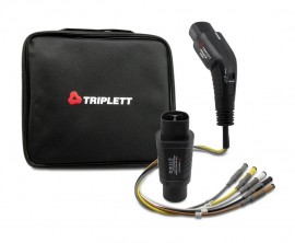
The Triplett Model TEV200 Electric Vehicle Probe Kit easily connects by wire (Standard Male Banana Type) between the EVSE charging point (Type-2 connector) and the measurement inputs of the DMM, Clamp or MFT. All wires of the charging connector are available: L1, L2, L3, N, PE, CP and PP.
The built-In Control Pilot (CP) state (vehicle simulation switch) can simulate vehicle states with different resistances connected between CP and PE conductors. You can use the CP Signal output terminals to connect your oscilloscope to check the waveform and amplitude of the CP signal. CP Error “E" simulates the behavior of the station when there is an established short circuit between CP and PE. The Probe Kit complies with EMC Directive (2014/30/EU), the Low Voltage Directive (2014/35/EU), and EN61010-1 standards.
Features
Applications
| General Specifications | |
| Input Voltage | 230/400 V 3 phase 50/60 Hz |
| Simulation | CP: States A, B, C PP: Setup internally to 20 A Error: CP error “E", PE (earth fault) error |
| Measurement Category | CAT II 300 V |
| Mains Socket Rating | Maz 10 A |
| Test Connector Type | IEC62196-2 Type 1 male (Male to Female adaptor included/Tesla) |
| Test Cable Length | 19.7" (0.5 m) |
| Power | Powered by Charging System |
| Dimensions | 7.7 x 4.2" (6 x 60 mm) |
| Weight | 14.0 oz (396 g) |
| Control Pilot (CP) State | |
| A (Vehicle not connected) |
CP–PE: open (∞) CP signal: ±12 V at 1 kHz |
| B (Vehicle connected, not ready to charge) |
CP–PE: 2.74 kΩ CP signal: +9 V / −12 V at 1 kHz |
| C (Vehicle connected, ready to charge, ventilation not required) |
CP–PE: 882 Ω CP signal: +6 V / −12 V at 1 kHz |
| E (CP error condition) |
CP–PE: 0 Ω CP signal: 0 V |
| Technical Specifications | |
| Input Voltage | UL1/N = 120 V, UL2/N = 120 V, UL1/L2 = 208 V, 60 Hz (three-phase system) or UL1/N = 120 V, UL2/N = 120 V, UL1/L2 = 240 V, 60 Hz (single-phase system), ±10% voltage fluctuations from nominal |
| EV Connector (EVC-13) | SAE J1772 (Type 1, 5P single phase) for measuring purpose Adapter SAEJ1772 to NACS for measurement purpose |
| Internal Power Consumption | N/A |
| Enviromental Conditions | Operating and storage temperature: -4 to 104°F (-20 to 40°C) Operating altitude: 6562' (2000 m) |
| Safety Standards | IEC 61010-1, Pollution degree 2 IEC61010-031 |
| Measurement Category | CAT II 300 V |
| IP Protection Class | IP40 |
| Functions | |
| Indication LEDs | N/A |
| CP States | A, B, C |
| CP Error “E" | On / Off |
| PE Error | N/A |
| GFCI Test | N/A |
| PE Pre-Test (Typical) | N/A |
| Outputs (for test purpose only) | |
| Measuring Terminals | Maximum 250 V 50/60 Hz, CAT II 300 V |
| L1, L2/N, PE | |
| CP Signal Output Terminals | Approximately ±12 V (under normal conditions), in case of wrong wiring or error of the charging station these terminals can be hazardous ≥ maximum 250 V against PE |