"Our job is helping you do your job"

Provide high-performance triggers and transparent color-coded decode overlays, protocol tables, and search capabilities to the T3DSO2000A series oscilloscopes.
Provide high-performance triggers and transparent color-coded decode overlays, protocol tables, and search capabilities to the T3DSO2000A series oscilloscopes.
Discontinued!
This product has been discontinued and is no longer available. There are no replacement options.
We can help you find what you need:
Features
Supports
Highly flexible and powerful triggering ("T")
The MIL-STD-1553 trigger can be configured at the transfer or word level to provide the right level of triggering. In addition, error triggers are able to locate the cause of protocol errors at either the transfer or word level. Word level triggering allows conditional RT Address and Sub Address entry.
Conditional DATA trigger setup ("T")
The trigger permits a conditional (<.>, >=, , inside a range, outside a range) setup for the DATA condition. This is especially useful in situations where abnormal events should be monitored.
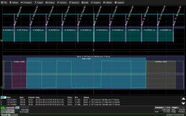
Intuitive, color-coded decode overlays ("D")
A transparent overlay with color-coding for specific portions of each protocol and the entire message frame makes it easy to understand your serial data information. Unlike other solutions, with protocol decode information away from the signal, our solution correlates the waveform and the protocol decode directly on the display. As the acquisition length is expanded or shortened, the decode overlay will adjust to show you just the right amount of information.
Interactive table summarizes results ("D")
Turn the oscilloscope into a protocol analyzer with a tabular display of decoded information. Customize the table to show only the data of interest and touch a message in the table to automatically zoom to it and display it on the screen. Export the table for offline analysis. Up to four different decoded signals of any type may be simultaneously displayed in the table.
Measure/graph tools for validation efficiency ("M")
Quickly validate cause and effect with automated timing measurements to or from an analog signal or another serial message. Make multiple measurements in a single long acquisition to quickly acquire statistics during corner-case testing. Serial (digital) data can be extracted to an analog value and graphed to monitor system performance over time, as if it was probed directly. Complete validation faster and gain better insight.
Eye diagrams ("P")
Rapidly display an eye diagram of your packetized low-speed serial data signal without additional setup time. Use eye parameters to quantify system performance and apply a standard or custom mask to identify anomalies. Mask failures can be indicated and can force the scope into Stop mode.
| Trigger Capability | |
| Format | Hexadecimal or Binary (Decimal for Word Count) |
| Trigger Setup | Trigger on ANY TRANSFER; a COMMAND WORD, STATUS WORD, DATA WORD, or ALL WORDS; an ERROR, a RESPONSE TIME, or an INTERMESSAGE GAP TIME. TRANSFERS may be further qualified by selecting the message type BC-RT, RT-BC, RT-RT, MODE COMMAND, MODE COMMAND & DATA (XMIT), MODE COMMAND AND DATA (RCV), various BROADCASTS (BC-RT(S), RT-RT(S), MODE COMMAND, and MODE COMMAND AND DATA) |
| Address Setup | For COMMAND WORD trigger specify 5-bit Remote Terminal (RT) Address ID(s) or Sub Address(es) with condition of <=, <, =, >, >=, <>, IN RANGE, OUT OF RANGE, or DON'T CARE; specify Transmit/Receive bit setting of 0, 1, or X (don't care) For STATUS WORD trigger, specify 5- bit RT Address(es) ID(s) with condition of <=, <, =, >, >=, <>, IN RANGE, OUT OF RANGE, or DON'T CARE; Specify Status Word bits as 0, 1, or X (don't care) for Message Error, Instrumentation, Service Request, Broadcast Command Received, Busy, Subsystem Flag, Dynamic Bus Control Acceptance, or Terminal Flag For any TRANSFER containing an RT Address or Sub Address, setup is identical to that specified above Settable in Hexadecimal or Binary format in all cases |
| DATA Setup | Data Word Count: In any TRANSFER, specify Data Word Count in decimal format up 32 data words DATA WORD or TRANSFER Data Setup (Hexadecimal): # Data Bytes = up to 2 (one Data Word) byte length, settable by nibble DATA WORD or TRANSFER Data Setup (Binary): Any combination of 0,1, or X for 1-16 bits Data pattern can be set to start at any location in an up to 2 Byte / 16 bit sequence (in a DATA WORD) or an up to 64 Byte / 512 bit sequence (in a TRANSFER) |
| DATA Condition Setup | Data Word Count: <=, <, =, >, >=, or <> Data Setup: <=, <, =, >, >=, <>, IN RANGE, OUT OF RANGE, or DON'T CARE |
| Mode Command Setup | TRANSFER MODE COMMANDS and COMMAND WORDS may be qualified by selecting a Mode Code (0 to 31, with description) with a Mode Code condition of <=, <, =, >, >=, or <> |
| Status Setup | In any TRANSFER or STATUS WORD, select 0, 1, or X (don't care) for various Status Word bits. Select for: Message Error, Instrumentation, Service Request, Broadcast Command Received, Busy, Subsystem Flag, Dynamic Bus Acceptance, and Terminal Flag |
| Error Setup | Select one or more Word Level or Transfer Level errors using a check box. Word Level error selection: Invalid Sync, Manchester Error, Idle Error, Parity Error Transfer Level error selection: Bad Word Count, Address Mismatch, Non-contiguous Data, Sync Error |
| Other Setups | Response Time Setup: Conditional Setup <, >, in range, out of range; Value Setup: 0 to 32.752 microseconds Intermessage Gap Setup: Conditional Setup <, >, in range, out of range; Value Setup: 0 to 32.752 microseconds |
| Bit Rates | 1 Mb/s, pre-defined nominal value |
| Trigger Input | Any analog Channel or the EXT input |
| Decode + Search Capability | |
| Format | Hexadecimal, Binary, Decimal (Binary not available for Address) |
| Decode Setup | Threshold definition required for High and Low levels. Default is to Absolute (in volts) amplitude Select Table (Display) Mode (WORD or TRANSFER) Define Response Time and InterMessage Gap Time limits |
| Decode Input | Any analog Channel, Memory or Math trace, and any Digital trace |
| Number of Decodes | Up to 4 buses may be decoded at one time. In addition, zooms can be displayed (with decoded information) |
| Visual Aid | Color Coding for Message, Word, Sync bits, RTA Address and SubAddress bits, Receive/Transmit bit, Data Count bits, Data (Payload) bytes and Single-bit Condition Codes, Reserved bits, Response Time Check and Inter-Message Gap Time, and Word and Transfer Level Error Codes Decode information is intelligently annotated based on timebase setting, and overlaid on acquired waveform |
| Table Configure, Export Table | Display 1 to 20 rows of decoded information for up to 4 different protocols or decodes in time order in a single table. Displayed information includes Index, Timestamp, and other various protocol-specific information. Table permits scrolling, touch to zoom, export to .csv file, and special display of long data or other patterns. |
| Pattern Search | Search for Previous or Next Index, Time, Message, Transaction, Type, Summary, Sync, RT Address, T/R, SubAddress, Count, ModeCode, Parity, Response Time, RT Address ACK, Message Error, Inst, SRQ, Reserved, Broadcase Rx, Busy, SubSystem Flag, Dynamic Bus Access, Terminal Flag, Data, IMG, or Status |