"Our job is helping you do your job"

Designed for frequency to current and voltage conversion, with output programmable to show period and pulse division or multiplication and buffering of fast pulse trains, this DIN rail signal conditioner provides AC/DC Supply, 0 KH to 20 kHz I/P, Frequency I/P & Process O/P Class.
Designed for frequency to current and voltage conversion, with output programmable to show period and pulse division or multiplication and buffering of fast pulse trains, this DIN rail signal conditioner provides AC/DC Supply, 0 KH to 20 kHz I/P, Frequency I/P & Process O/P Class.
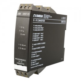
Programmable f/I - f/f converter that performs frequency to current and voltage conversion. Typical pulse sources are flow meters, tacho generators, mechanical switches, or inductive proximity sensors. The f/f function can be used for pulse division or multiplication and as a buffer collecting fast pulse trains.
Features
Applications
| Series | DRST-FR Series |
| Type | DIN rail signal conditioner |
| Supply voltage | AC/DC Supply |
| Input | 0 KH to 20 kHz I/P |
| Input | Frequency I/P & Process O/P Class |
| Supply voltage | 19.2...300 V DC / 21.6...253 V AC |
| Frequency | 50...60 Hz |
| Fuse | 400 mA T / 250 V AC |
| Internal consumption | 3 W |
| Maximum consumption | 3.5 W |
| Isolation, test / operation | 3.75 kV AC / 250 V AC |
| Power up delay | 0...999 s |
| Warm-up time | 1 minute |
| Communications interface | Loop Link |
| Signal / noise ratio | Minimum 60 dB |
| Signal dynamics, output | 16 bit |
| Frequency measurement range | 0...20 kHz |
| Minimum measurement range | 0.001 Hz |
| Current output signal range | 0...20 mA |
| Voltage output signal range | 0...10 V DC |
| Response time, analogue | < 60 ms + period |
| Response time, digital output | < 50 ms + period |
| Temperature coefficient | < ±0.01% of span / °C |
| Linearity error | < ±0.1% of span |
| Effect of supply voltage change | < 0.005% of span / V DC |
| EMC immunity influence | < ±0.5% |
| DIN rail type | DIN 46277 |
| Protection degree | IP20 |
| Maximum wire size | 1 x 2.5 mm2 stranded wire |
| Screw terminal torque | 4.43 in-lb (0.5 Nm) |
| Specifications range | -4 to 140°F (-20 to 60°C) |
| Calibration temperature | 68 to 82°F (20 to 28°C) |
| Air humidity | < 95% RH (non-condensing) |
| Max. consumption | 3.5 W |
| NAMUR supply | 8.3 VDC ± 0.5 VDC / 8 mA |
| NAMUR supply EEx | 8.5 VDC ± 0.5 VDC / 8 mA |
| S0 supply | 17 VDC / 20 mA |
| NPN / PNP supply | 17 VDC / 20 mA |
| Special supply (programmable) | 5...17 VDC / 20 mA |
| Measurement range | 0...20 kHz |
| Min. measurement range | 0.001 Hz |
| Max. offset | 90% of selected maximum. frequency |
| Min. pulse width (without filter) | 25 μs |
| Min. period (without filter) | 50 μs |
| Max. frequency (without filter) | 20 kHz |
| Min. pulse width (with filter) | 10 ms |
| Min. period (with filter) | 20 ms |
| Max. frequency (with filter) | 50 Hz |
| Programmable trig level | 0.025...6.5 V (nom.), 1...8 mA (nom.) |
| NAMUR input (DIN 19234), trig-level LOW | ≤ 1.2 mA |
| NAMUR input (DIN 19234), trig-level HIGH | ≥ 2.1 mA |
| NAMUR input impedance | 1000 Ω |
| NAMUR sensor error detection, breakage | ≤ 0.1 mA |
| NAMUR sensor error detection, short-circuit | ≥ 7.0 mA |
| NAMUR sensor error detection, response time | ≥ 400 ms |
| Tacho input, trig-level LOW | ≤ -40 mV |
| Tacho input, trig-level HIGH | ≥ 40 mV |
| Tacho input impedance | ≥ 100 kΩ |
| Tacho input, maximum. input voltage | 80 VAC pp |
| NPN / PNP input, trig-level LOW | ≤ 4.0 V |
| NPN / PNP input, trig-level HIGH | ≥ 7.0 V |
| NPN / PNP input impedance, standard | 3.48 kΩ |
| NPN / PNP input impedance, special version | 3.48...12 kΩ |
| 2-phase encoder, minimum. pulse width (without filter) | 1 ms |
| 2-phase encoder, minimum. period (without filter) | 2 ms |
| 2-phase encoder, maximum. frequency (without filter) | 500 Hz |
| TTL input, trig-level LOW | ≤ 0.8 VDC |
| TTL input, trig-level HIGH | ≥ 2.0 VDC |
| TTL input impedance | ≥ 100 kΩ |
| S0 input (DIN 43 864), trig-level LOW | ≤ 2.2 mA |
| S0 input (DIN 43 864), trig-level HIGH | ≥ 9.0 mA |
| S0 input impedance | 800 Ω |
| Current output, minimum. signal range | 5 mA |
| Current output, maximum. offset | 50% of selected maximum. value |
| Current output, updating time | 20 ms |
| Current output, load (maximum.) | 20 mA / 600 Ω / 12 VDC |
| Current output, load stability | < ± 0.01% of span / 100 Ω |
| Current output, current limit | ≤ 23 mA |
| Voltage output through internal shunt, signal range | 0...10 VDC |
| Voltage output, minimum. signal span | 250 mV |
| Voltage output, maximum. offset | 50% of selected maximum. value |
| Voltage output, load (minimum.) | 500 kΩ |
| Active outputs (NPN / PNP), Imax. source | 10 mA |
| Active outputs (NPN / PNP), Imax. sink | 130 mA |
| Active outputs (NPN / PNP), Vmax. | 28 VDC |
| f/f converter output, signal range | 0...1000 Hz |
| f/f converter output, minimum. pulse width | 500 μs |
| f/f converter output, maximum. pulse width | 999 ms |
| f/f converter output, maximum. duty cycle | 0.5 |
| Frequency generator, minimum. period | 50 μs |
| Frequency generator, maximum. frequency | 20 kHz |
| Frequency generator, duty cycle | 0.5 |
| Relay output, frequency maximum. | 20 Hz |
| Relay output, Vmax. | 250 VRMS |
| Relay output, Imax. | 2 A / AC |
| Relay output, maximum. AC power | 500 VA |
| Relay output, maximum. AC power Ex version | 100 VA |
| Relay output, maximum. load at 24 VDC | 0.04166666666666666 |
| Max. wire size | 1 x 2,5 mm2 stranded wire |
| Installation | Installation Category II, Pollution Degree 1, Insulation Class II |
| EEx / I.S. approval | KEMA 04ATEX1001 II (1) GD [EEx ia] IIC; applicable in zone 0, 1, 2, 20, 21 or 22 |
| Observed authority requirements, EMC | 2004/108/EC, EN 61326-1 |
| Observed authority requirements, LVD | 2006/95/EC, EN 61010-1 |
| Observed authority requirements, PELV/SELV | IEC 364-4-41 and EN 60742 |
| Observed authority requirements, ATEX | 94/9/EC, EN 50014, EN 50020 and EN 50284 |
| Dimensions (H x W x D) | 4.29 x 0.93 x 5.12" (109 x 23.5 x 130 mm) |
| Weight | 8.82 oz (250 g) |
Click on a category to view a selection of compatible accessories with the Omega DRST-FR DIN Rail Signal Conditioner, frequency input, process output.

| Series | DRST-FR Series |
| Type | DIN rail signal conditioner |
| Supply voltage | AC/DC Supply |
| Input | 0 KH to 20 kHz I/P |
| Input | Frequency I/P & Process O/P Class |
| Supply voltage | 19.2...300 V DC / 21.6...253 V AC |
| Frequency | 50...60 Hz |
| Fuse | 400 mA T / 250 V AC |
| Internal consumption | 3 W |
| Maximum consumption | 3.5 W |
| Isolation, test / operation | 3.75 kV AC / 250 V AC |
| Power up delay | 0...999 s |
| Warm-up time | 1 minute |
| Communications interface | Loop Link |
| Signal / noise ratio | Minimum 60 dB |
| Signal dynamics, output | 16 bit |
| Frequency measurement range | 0...20 kHz |
| Minimum measurement range | 0.001 Hz |
| Current output signal range | 0...20 mA |
| Voltage output signal range | 0...10 V DC |
| Response time, analogue | < 60 ms + period |
| Response time, digital output | < 50 ms + period |
| Temperature coefficient | < ±0.01% of span / °C |
| Linearity error | < ±0.1% of span |
| Effect of supply voltage change | < 0.005% of span / V DC |
| EMC immunity influence | < ±0.5% |
| DIN rail type | DIN 46277 |
| Protection degree | IP20 |
| Maximum wire size | 1 x 2.5 mm2 stranded wire |
| Screw terminal torque | 4.43 in-lb (0.5 Nm) |
| Specifications range | -4 to 140°F (-20 to 60°C) |
| Calibration temperature | 68 to 82°F (20 to 28°C) |
| Air humidity | < 95% RH (non-condensing) |
| Max. consumption | 3.5 W |
| NAMUR supply | 8.3 VDC ± 0.5 VDC / 8 mA |
| NAMUR supply EEx | 8.5 VDC ± 0.5 VDC / 8 mA |
| S0 supply | 17 VDC / 20 mA |
| NPN / PNP supply | 17 VDC / 20 mA |
| Special supply (programmable) | 5...17 VDC / 20 mA |
| Measurement range | 0...20 kHz |
| Min. measurement range | 0.001 Hz |
| Max. offset | 90% of selected maximum. frequency |
| Min. pulse width (without filter) | 25 μs |
| Min. period (without filter) | 50 μs |
| Max. frequency (without filter) | 20 kHz |
| Min. pulse width (with filter) | 10 ms |
| Min. period (with filter) | 20 ms |
| Max. frequency (with filter) | 50 Hz |
| Programmable trig level | 0.025...6.5 V (nom.), 1...8 mA (nom.) |
| NAMUR input (DIN 19234), trig-level LOW | ≤ 1.2 mA |
| NAMUR input (DIN 19234), trig-level HIGH | ≥ 2.1 mA |
| NAMUR input impedance | 1000 Ω |
| NAMUR sensor error detection, breakage | ≤ 0.1 mA |
| NAMUR sensor error detection, short-circuit | ≥ 7.0 mA |
| NAMUR sensor error detection, response time | ≥ 400 ms |
| Tacho input, trig-level LOW | ≤ -40 mV |
| Tacho input, trig-level HIGH | ≥ 40 mV |
| Tacho input impedance | ≥ 100 kΩ |
| Tacho input, maximum. input voltage | 80 VAC pp |
| NPN / PNP input, trig-level LOW | ≤ 4.0 V |
| NPN / PNP input, trig-level HIGH | ≥ 7.0 V |
| NPN / PNP input impedance, standard | 3.48 kΩ |
| NPN / PNP input impedance, special version | 3.48...12 kΩ |
| 2-phase encoder, minimum. pulse width (without filter) | 1 ms |
| 2-phase encoder, minimum. period (without filter) | 2 ms |
| 2-phase encoder, maximum. frequency (without filter) | 500 Hz |
| TTL input, trig-level LOW | ≤ 0.8 VDC |
| TTL input, trig-level HIGH | ≥ 2.0 VDC |
| TTL input impedance | ≥ 100 kΩ |
| S0 input (DIN 43 864), trig-level LOW | ≤ 2.2 mA |
| S0 input (DIN 43 864), trig-level HIGH | ≥ 9.0 mA |
| S0 input impedance | 800 Ω |
| Current output, minimum. signal range | 5 mA |
| Current output, maximum. offset | 50% of selected maximum. value |
| Current output, updating time | 20 ms |
| Current output, load (maximum.) | 20 mA / 600 Ω / 12 VDC |
| Current output, load stability | < ± 0.01% of span / 100 Ω |
| Current output, current limit | ≤ 23 mA |
| Voltage output through internal shunt, signal range | 0...10 VDC |
| Voltage output, minimum. signal span | 250 mV |
| Voltage output, maximum. offset | 50% of selected maximum. value |
| Voltage output, load (minimum.) | 500 kΩ |
| Active outputs (NPN / PNP), Imax. source | 10 mA |
| Active outputs (NPN / PNP), Imax. sink | 130 mA |
| Active outputs (NPN / PNP), Vmax. | 28 VDC |
| f/f converter output, signal range | 0...1000 Hz |
| f/f converter output, minimum. pulse width | 500 μs |
| f/f converter output, maximum. pulse width | 999 ms |
| f/f converter output, maximum. duty cycle | 0.5 |
| Frequency generator, minimum. period | 50 μs |
| Frequency generator, maximum. frequency | 20 kHz |
| Frequency generator, duty cycle | 0.5 |
| Relay output, frequency maximum. | 20 Hz |
| Relay output, Vmax. | 250 VRMS |
| Relay output, Imax. | 2 A / AC |
| Relay output, maximum. AC power | 500 VA |
| Relay output, maximum. AC power Ex version | 100 VA |
| Relay output, maximum. load at 24 VDC | 0.04166666666666666 |
| Max. wire size | 1 x 2,5 mm2 stranded wire |
| Installation | Installation Category II, Pollution Degree 1, Insulation Class II |
| EEx / I.S. approval | KEMA 04ATEX1001 II (1) GD [EEx ia] IIC; applicable in zone 0, 1, 2, 20, 21 or 22 |
| Observed authority requirements, EMC | 2004/108/EC, EN 61326-1 |
| Observed authority requirements, LVD | 2006/95/EC, EN 61010-1 |
| Observed authority requirements, PELV/SELV | IEC 364-4-41 and EN 60742 |
| Observed authority requirements, ATEX | 94/9/EC, EN 50014, EN 50020 and EN 50284 |
| Dimensions (H x W x D) | 4.29 x 0.93 x 5.12" (109 x 23.5 x 130 mm) |
| Weight | 8.82 oz (250 g) |
Click on a category to view a selection of compatible accessories with the Omega DRST-FR DIN Rail Signal Conditioner, frequency input, process output.