"Our job is helping you do your job"

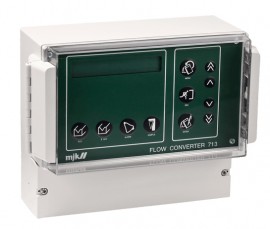
For use with the open channel flow meter, the flow converter comes with a 0 to 10' measurement range.
For use with the open channel flow meter, the flow converter comes with a 0 to 10' measurement range.
Discontinued!
This product has been discontinued and is no longer available. There are no replacement options.
We can help you find what you need:
Ideal for measuring and calculating water flow in open ducts and channels, this open channel flow meter is a comprehensive instrument for measuring the instantaneous flow and recording the totalized water flow. In addition, the sensor provides a signal proportional to the level and the amplifier linearizes the signal from the sensor so it is proportional to the flow rate.
Features
Applications
| Measuring Range | 0 to 10' (0 to 3.04 m) |
| Temperature | -5 to 150°F (-20.55 to 65.55°C) |
| Input Signal | From ultrasonic sensor, pressure transmitter or other 4 to 20 mA |
| Digital Outputs | Terminals 6 to 17: relay 1 to 4, maximum 250 V, 4 A resistive load, maximum 100 V A inductive load Can be chosen as alarm, counter, flow >0 or sampler outputs Terminals 18 to 20: relay 5 pulse (optocoupler) maximum 36 V, 50 mA one shot, 100 msecond to 10 second programmable |
| Analogue Output | Terminals 21 to 22: Active, 0 to 20/4 to 20 mA, maximum 500 Ω, galvanic isolation |
| Calculation | Standard formulas according to ASTM standards and US Department of the Interior Optional formula Q = C × hx or 10 point level to flow curve linearization |
| Indication | 2 x 24 characters LCD display for readout and programming |
| Accuracy | ≤ ±1% |
| Resolution | Minimum ±0.04" (1.01 mm) |
| Materials | House and cover: Polystyrol |
| Enclosure Rating | NEMA 4X |
| Supply | 110 to 120 V AC or 24 V DC approximately 10 V A |
| Dimensions | 7.28 × 9.45 × 4.53" (18.49 x 24 x 11.5 cm) |