"Our job is helping you do your job"


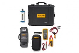
The Fluke FLK-GFL1500-283/PV kit pairs the GFL-1500 ground fault locator with the 283FC/PV TRMS multimeter and wireless current clamp, providing a complete toolkit for identifying and diagnosing ground faults in solar arrays. It is a professional solar PV ground fault troubleshooting kit designed for high-voltage photovoltaic systems up to 1500 V DC and is essential for maintaining system uptime and safety, allowing quick fault location and comprehensive electrical system analysis.
The Fluke FLK-GFL1500-283/PV kit pairs the GFL-1500 ground fault locator with the 283FC/PV TRMS multimeter and wireless current clamp, providing a complete toolkit for identifying and diagnosing ground faults in solar arrays. It is a professional solar PV ground fault troubleshooting kit designed for high-voltage photovoltaic systems up to 1500 V DC and is essential for maintaining system uptime and safety, allowing quick fault location and comprehensive electrical system analysis.
The main benefit of the Fluke FLK-GFL1500-283/PV is that it helps solar technicians find and diagnose PV ground faults faster, safer, and with less guesswork. By combining precise ground fault locating with 1500 V-rated voltage testing and wireless current measurement, the kit reduces troubleshooting time, limits unnecessary system disconnection, improves technician safety, and helps restore solar system uptime more efficiently. It is a complete field-ready solution for PV maintenance teams that need reliable tools for high-voltage solar fault detection, electrical analysis, and system performance troubleshooting.
GFL-1500 Solar Ground Fault Locator
283 FC/PV Solar Digital Multimeter and Wireless Current Clamp
Applications
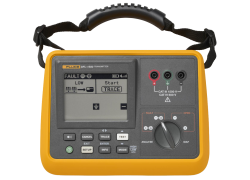
The Fluke GFL-1500 Solar Ground Fault Locator is a frontline troubleshooting tool that helps technicians quickly pinpoint active ground faults in solar photovoltaic (PV) systems. It works by producing a traceable signal in the array, allowing for fast, intuitive, non-contact tracing directly to the fault location.

Whether you're performing frontline troubleshooting on a utility-scale PV array, wind power installation, electric railways, or data centers, this kit is the perfect troubleshooting combination for technicians in DC environments up to 1500 V. In addition, this kit enhances safety and increases productivity while giving you accurate, reliable, and repeatable results.
 In the past, motor repair meant dealing with traditional three-phase motor failures that were largely the result of water, dust, grease, failed bearings, misaligned motor shafts, or just plain old age. But motor repair has changed in a big way with the introduction of electronically controlled motors, more commonly referred to as adjustable speed drives (ASDs). These drives present a unique set of measurement problems that can vex the most seasoned pro. Thanks to new technology, now for the first time you can take accurate electrical measurements with a DMM during the installation and maintenance of a drive and diagnose bad components and other conditions that may lead to premature failure.

Technicians use many different methods to troubleshoot an electrical circuit, and a good troubleshooter will always find the problem - eventually. The trick is tracking it down quickly and keeping downtime to a minimum. The most efficient troubleshooting procedure begins at the motor and then works systematically back to the electrical source, looking for the most obvious problems first. A lot of time and money can be wasted replacing perfectly good parts when the problem is simply a loose connection. As you go, take care to take accurate measurements. Nobody takes inaccurate measurements on purpose, but it's easy to do, especially when working in a high-energy, noisy environment like an ASD. Likewise, choosing the right test tools for troubleshooting the drive, the motor, and the connections are of utmost importance. This is especially true when taking voltage, frequency, and current measurements on the output side of the motor drive. But until now, there hasn't been a digital multimeter on the market able to accurately measure ASDs. Incorporates a selectable low pass filter* that allows for accurate drive output measurements that agree with the motor drive controller display indicator. Now, technicians won't have to guess whether the drive is operating correctly and delivering the correct voltage, current, or frequency for a given control setting.
Input side measurements
Any good quality True RMS multimeter can verify proper input power to an ASD. The input voltage readings should be within 1% of one another when measured from phase to phase with no load. A significant unbalance may lead to erratic drive operation and should be corrected when discovered.

Output side measurements
On the flip side, a regular True RMS multimeter can't reliably read the output side of a pulse width modulated (PWM) motor drive, because the ASD applies pulse width modulated nonsinusoidal voltage to the motor terminals. A True RMS DMM reads the heating effect of the non-sinusoidal voltage applied to the motor, while the motor controller's output voltage reading only displays the RMS value of the fundamental component (typically from 30 Hz to 60 Hz). The causes of this discrepancy are bandwidth and shielding. Many of today's True RMS digital multimeters have bandwidths out to 20 kHz or more, causing them to respond not only to the fundamental component, which is what the motor responds to but to all of the high-frequency components generated by the PWM drive. And if the DMM isn't shielded for high-frequency noise, the drive controller's high noise levels make the measurement discrepancies even more extreme. With the bandwidth and shielding issues combined, many True RMS meters display readings as much as 20 to 30% higher than what the drive controller is indicating. The incorporated selectable low pass filter allows troubleshooters to take accurate voltage, current, and frequency measurements on the output side of the drive at either the drive itself or the motor terminals. With the filter selected, the readings for both voltage and frequency (motor speed) should agree with the associated drive control display indications, if available. The low pass filter also allows for accurate current measurements when used with Hall-effect type clamps. All of these measurements are especially helpful when taking measurements at the motor location when the drive's displays are not in view.
Taking safe measurements
Before taking any electrical measurements, be sure you understand how to take them safely. No test instrument is completely safe if used improperly, and many test instruments are not appropriate for testing adjustable speed drives. Also, make sure to use the appropriate personal protective equipment (PPE) for your specific working environment and measurements. If at all possible, never work alone.


Safety ratings for electrical test equipment
ANSI and the International Electrotechnical Commission (IEC) are the primary independent organizations that define safety standards for test equipment manufacturers. The IEC 61010 second edition standard for test equipment safety states two basic parameters: a voltage rating and a measurement category rating. The voltage rating is the maximum continuous working voltage the instrument is capable of measuring. The category ratings depict the measurement environment expected for a given category. Most three-phase ASD installations would be considered a CAT III measurement environment, with power supplied from either 480V or 600V distribution systems. When using a DMM for measurements on these high-energy systems, make sure it's rated at a minimum for CAT III 600V and preferably for CAT IV 600V/CAT III 1000V. The category rating and voltage limit are typically found on the front panel, at the input terminals. Dual-rated CAT IV 600V and CAT III 1000V. Refer to the ABC's of DMM Safety* from Fluke for additional information on category ratings and taking safe measurements.
Now let's put the multimeter to the test. The measurements in the following procedure are designed to be made on a 480 volt 3 phase drive control at the control panel terminal strips. These procedures would also be valid for lower voltage 3 phase drives powered by either single or 3 phase supply voltages. For these tests, the motor is running at 50 Hz.
Input voltage
To measure the ac voltage supply to the input side of the drive at the drive:
Input current
Measuring the input current generally requires a current clamp accessory. In most cases, either the input current exceeds the maximum current measurable by the current function, or it isn't practical to "break the circuit" to take an in-line series current measurement. Regardless of clamp type, insure that all readings are within 10% of each other for proper balance.
Transformer type clamp (i200, 80i-400, 80i-600A)
Hall Effect type (AC/DC) clamp (i410,i-1010)
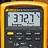
Figure 1. Output voltage reading without using the low pass filter.


Figure 2. Output voltage reading with low pass filter enabled.
Output voltage
To measure the AC output voltage at either the drive or the motor terminals:
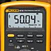
Figure 3. Output frequency (motor speed) without the low pass filter.
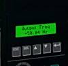
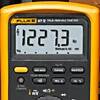
Figure 4. Output frequency (motor speed) using the low pass filter.
Motor speed (Output frequency using voltage as a reference)
To determine motor speed, simply take a frequency measurement while using the low pass filter. The measurement can be made between any two of the phase voltage or motor terminals.
Output current
TAs with input current, measuring the output current generally requires a current clamp accessory. Once again, regardless of clamp type, insure that all readings are within 10% of each other for proper balance.
Transformer type clamp (i200, 80i-400, 80i-600A)
Figure 5. Output current reading without using the low pass filter.

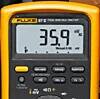
Figure 6. Output current reading with low pass filter enabled.

Hall Effect type (AC/DC) clamp (i410,i-1010)
Motor speed (Output frequency using current as a reference)
For motors that pull at least 20 amps of running current, motor speed can be determined by taking a frequency measurement with current clamps. Until now, noise issues have prevented accurate readings using hall effect type clamps. Here's how the low pass filter makes it possible.
Motor speed using a Hall Effect type (AC/DC) clamp (i410,i-1010)
Motor speed using a transformer type clamp (i200, 80i-400, 80i-600A)
DC Bus measurements
A healthy dc bus is a must for a properly operating motor drive. If the bus voltage is incorrect or unstable, the converter diodes or capacitors may be starting to fail. The DC bus voltage should be approximately 1.414 times the phase to phase input voltage. For a 480 volt input, the DC bus should be approximately 679 VDC. The DC bus is typically labeled as DC+, DC- or B+, Bon the drive terminal strip. To measure the DC bus voltage:
The Fluke GFL-1500 Solar Ground Fault Locator is a frontline troubleshooting tool that helps technicians quickly pinpoint active ground faults in solar photovoltaic (PV) systems. It works by producing a traceable signal in the array, allowing for fast, intuitive, non-contact tracing directly to the fault location.
Whether you're performing frontline troubleshooting on a utility-scale PV array, wind power installation, electric railways, or data centers, this kit is the perfect troubleshooting combination for technicians in DC environments up to 1500 V. In addition, this kit enhances safety and increases productivity while giving you accurate, reliable, and repeatable results.
In the past, motor repair meant dealing with traditional three-phase motor failures that were largely the result of water, dust, grease, failed bearings, misaligned motor shafts, or just plain old age. But motor repair has changed in a big way with the introduction of electronically controlled motors, more commonly referred to as adjustable speed drives (ASDs). These drives present a unique set of measurement problems that can vex the most seasoned pro. Thanks to new technology, now for the first time you can take accurate electrical measurements with a DMM during the installation and maintenance of a drive and diagnose bad components and other conditions that may lead to premature failure.
Technicians use many different methods to troubleshoot an electrical circuit, and a good troubleshooter will always find the problem - eventually. The trick is tracking it down quickly and keeping downtime to a minimum. The most efficient troubleshooting procedure begins at the motor and then works systematically back to the electrical source, looking for the most obvious problems first. A lot of time and money can be wasted replacing perfectly good parts when the problem is simply a loose connection. As you go, take care to take accurate measurements. Nobody takes inaccurate measurements on purpose, but it's easy to do, especially when working in a high-energy, noisy environment like an ASD. Likewise, choosing the right test tools for troubleshooting the drive, the motor, and the connections are of utmost importance. This is especially true when taking voltage, frequency, and current measurements on the output side of the motor drive. But until now, there hasn't been a digital multimeter on the market able to accurately measure ASDs. Incorporates a selectable low pass filter* that allows for accurate drive output measurements that agree with the motor drive controller display indicator. Now, technicians won't have to guess whether the drive is operating correctly and delivering the correct voltage, current, or frequency for a given control setting.
Input side measurements
Any good quality True RMS multimeter can verify proper input power to an ASD. The input voltage readings should be within 1% of one another when measured from phase to phase with no load. A significant unbalance may lead to erratic drive operation and should be corrected when discovered.
Output side measurements
On the flip side, a regular True RMS multimeter can't reliably read the output side of a pulse width modulated (PWM) motor drive, because the ASD applies pulse width modulated nonsinusoidal voltage to the motor terminals. A True RMS DMM reads the heating effect of the non-sinusoidal voltage applied to the motor, while the motor controller's output voltage reading only displays the RMS value of the fundamental component (typically from 30 Hz to 60 Hz). The causes of this discrepancy are bandwidth and shielding. Many of today's True RMS digital multimeters have bandwidths out to 20 kHz or more, causing them to respond not only to the fundamental component, which is what the motor responds to but to all of the high-frequency components generated by the PWM drive. And if the DMM isn't shielded for high-frequency noise, the drive controller's high noise levels make the measurement discrepancies even more extreme. With the bandwidth and shielding issues combined, many True RMS meters display readings as much as 20 to 30% higher than what the drive controller is indicating. The incorporated selectable low pass filter allows troubleshooters to take accurate voltage, current, and frequency measurements on the output side of the drive at either the drive itself or the motor terminals. With the filter selected, the readings for both voltage and frequency (motor speed) should agree with the associated drive control display indications, if available. The low pass filter also allows for accurate current measurements when used with Hall-effect type clamps. All of these measurements are especially helpful when taking measurements at the motor location when the drive's displays are not in view.
Taking safe measurements
Before taking any electrical measurements, be sure you understand how to take them safely. No test instrument is completely safe if used improperly, and many test instruments are not appropriate for testing adjustable speed drives. Also, make sure to use the appropriate personal protective equipment (PPE) for your specific working environment and measurements. If at all possible, never work alone.
Safety ratings for electrical test equipment
ANSI and the International Electrotechnical Commission (IEC) are the primary independent organizations that define safety standards for test equipment manufacturers. The IEC 61010 second edition standard for test equipment safety states two basic parameters: a voltage rating and a measurement category rating. The voltage rating is the maximum continuous working voltage the instrument is capable of measuring. The category ratings depict the measurement environment expected for a given category. Most three-phase ASD installations would be considered a CAT III measurement environment, with power supplied from either 480V or 600V distribution systems. When using a DMM for measurements on these high-energy systems, make sure it's rated at a minimum for CAT III 600V and preferably for CAT IV 600V/CAT III 1000V. The category rating and voltage limit are typically found on the front panel, at the input terminals. Dual-rated CAT IV 600V and CAT III 1000V. Refer to the ABC's of DMM Safety* from Fluke for additional information on category ratings and taking safe measurements.
Now let's put the multimeter to the test. The measurements in the following procedure are designed to be made on a 480 volt 3 phase drive control at the control panel terminal strips. These procedures would also be valid for lower voltage 3 phase drives powered by either single or 3 phase supply voltages. For these tests, the motor is running at 50 Hz.
Input voltage
To measure the ac voltage supply to the input side of the drive at the drive:
Input current
Measuring the input current generally requires a current clamp accessory. In most cases, either the input current exceeds the maximum current measurable by the current function, or it isn't practical to "break the circuit" to take an in-line series current measurement. Regardless of clamp type, insure that all readings are within 10% of each other for proper balance.
Transformer type clamp (i200, 80i-400, 80i-600A)
Hall Effect type (AC/DC) clamp (i410,i-1010)
Figure 1. Output voltage reading without using the low pass filter.
Figure 2. Output voltage reading with low pass filter enabled.
Output voltage
To measure the AC output voltage at either the drive or the motor terminals:
Figure 3. Output frequency (motor speed) without the low pass filter.
Figure 4. Output frequency (motor speed) using the low pass filter.
Motor speed (Output frequency using voltage as a reference)
To determine motor speed, simply take a frequency measurement while using the low pass filter. The measurement can be made between any two of the phase voltage or motor terminals.
Output current
TAs with input current, measuring the output current generally requires a current clamp accessory. Once again, regardless of clamp type, insure that all readings are within 10% of each other for proper balance.
Transformer type clamp (i200, 80i-400, 80i-600A)
Figure 5. Output current reading without using the low pass filter.
Figure 6. Output current reading with low pass filter enabled.
Hall Effect type (AC/DC) clamp (i410,i-1010)
Motor speed (Output frequency using current as a reference)
For motors that pull at least 20 amps of running current, motor speed can be determined by taking a frequency measurement with current clamps. Until now, noise issues have prevented accurate readings using hall effect type clamps. Here's how the low pass filter makes it possible.
Motor speed using a Hall Effect type (AC/DC) clamp (i410,i-1010)
Motor speed using a transformer type clamp (i200, 80i-400, 80i-600A)
DC Bus measurements
A healthy dc bus is a must for a properly operating motor drive. If the bus voltage is incorrect or unstable, the converter diodes or capacitors may be starting to fail. The DC bus voltage should be approximately 1.414 times the phase to phase input voltage. For a 480 volt input, the DC bus should be approximately 679 VDC. The DC bus is typically labeled as DC+, DC- or B+, Bon the drive terminal strip. To measure the DC bus voltage: